western
Physics and Astronomy


Circuitous Circuits
ObjectiveTo identify the circuit diagrams of five "Black Boxes".
ParticipantsTeams of up to six.
MaterialsFive "Black Boxes" each consisting of five light bulbs connected to two terminals by concealed wiring.
Paper, pencil, 12 volt power supply. SL 1483 light bulbs - 6 V, 0.04 A
Rules

1. Teams will be provided with a work area, five Black Boxes and two variable voltage power supplies.

2. Two power supplies will be available for each work area and as a result two Black Boxes can be analysed at a time. Only one Black Box can be connected to any given power supply at a time.

3. After analysing the circuit, the terminals and their connections to the five light bulbs will be neatly drawn in the form of a schematic diagram. It is not necessary to determine the order in which the components of the circuit are arranged. i.e. the circuit may consist of a group of three lights that are in parallel with the other two lights connected in series. It is not necessary in this event to say whether the parallel component is between the two in series or on either end.

4. The circuit diagrams with all of the proper components included regardless of the order of arrangement will be considered correct.

5. The maximum time limit allowed is 30 minutes. The finish time will be recorded.

6. The finish time occurs at the instant all five of the circuit diagrams are collectively handed to the judge.

Procedure

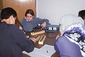
1. Ensure that the variable power supply is turned off and that the output voltage knob is turned to its lowest limit.

2. Connect the power supply to the two terminals.

3. Turn on the power supply and slowly increase the voltage until all of the lights are just lit. Leave the voltage at this level and do not adjust it further for this black box. Keep the voltage constant at this value throughout this experiment.

4. Selectively unscrew the light bulbs to determine which of them are connected in series and which in parallel.

5. After ascertaining how the light bulbs are connected, complete a circuit diagram.

6. Turn the voltage down on the variable power supply and turn it off.

7. Disconnect the leads from black box 1 and proceed to analyse in a similar fashion the remaining black boxes.

8. After completing the circuit diagrams for all five Black Boxes immediately have one member of the team take the diagrams to the judges.

9. Ensure that before leaving your test area that it is as you found it. The power supply should be turned off and down. It should not be connected to any of the black boxes. The area should be neat and tidy.

Judging

Up to 80 points will be awarded for the number of circuits identified correctly as follows:

# of Circuits Correct
Score
1
10
2
20
3
40
4
60
5
80

Up to 20 points will be awarded based on the time taken by your team to complete the event, as follows:

Your time points = ((Longest time - Your time) / (Longest time - Shortest time)) x 20

This formula gives 20 time points to the fastest team, zero time points to the slowest team, and a proportional score to the rest.

Typical Circuit
SourceLondon District Science Olympics. This event was designed by Dennis Trankner and John Welbourn. The mystery boxes were built by Perry Caskanette.

Events | Location | Scheduling | Registration | Participants | Committee | Judges and Officials | Scoring | Awards | Media
Contact Us | Our Sponsors | Faculty of Science | Western

© 2001 The University of Western Ontario,
Department of Physics and Astronomy

Webmaster: Patrick Whippey
Site Design: Julie Whitehead